 Having
built Push Pull amplifiers, I decided that it was time I took a serious look at why
single ended designs have become so widely appreciated. Being used to PP power,
the natural choice for me was the 845. (I now know what can be done with
2-5W amplifiers and efficient speakers but I had committed to this project
before that particular lesson had sunk in.) The RCA data sheet states
that 23W can be developed into 7600 Ohms. I studied the curves carefully
and initially decided to go with 10,000 Ohms to allow for speaker impedance dips.
(The final design ended up at 11k.) I
also decided to use this project as an opportunity to get my head around the
design and construction of output transformers. This project, in the way
of ambitious tube projects is physically large. It is built on two chassis
of 19" x 15". The power supply is on one chassis, the amplifier
on the other. You can see details of the topology by clicking on the
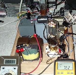
hyperlinks below the topology description. The picture shows a close up of the 845 "in heat", note B+ voltage and bias (measured
across 10 Ohms). I had been listening to this kluge (in mono) and amazingly
it sounded really good. I am now totally won over to SE. (I noticed
after I took the picture that I had powered up without the speaker connected!
This is NOT recommended.)
Having
built Push Pull amplifiers, I decided that it was time I took a serious look at why
single ended designs have become so widely appreciated. Being used to PP power,
the natural choice for me was the 845. (I now know what can be done with
2-5W amplifiers and efficient speakers but I had committed to this project
before that particular lesson had sunk in.) The RCA data sheet states
that 23W can be developed into 7600 Ohms. I studied the curves carefully
and initially decided to go with 10,000 Ohms to allow for speaker impedance dips.
(The final design ended up at 11k.) I
also decided to use this project as an opportunity to get my head around the
design and construction of output transformers. This project, in the way
of ambitious tube projects is physically large. It is built on two chassis
of 19" x 15". The power supply is on one chassis, the amplifier
on the other. You can see details of the topology by clicking on the
hyperlinks below the topology description. The picture shows a close up of the 845 "in heat", note B+ voltage and bias (measured
across 10 Ohms). I had been listening to this kluge (in mono) and amazingly
it sounded really good. I am now totally won over to SE. (I noticed
after I took the picture that I had powered up without the speaker connected!
This is NOT recommended.)
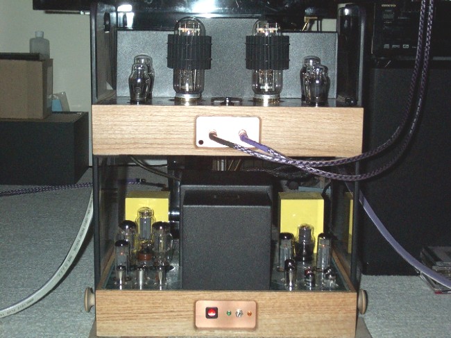
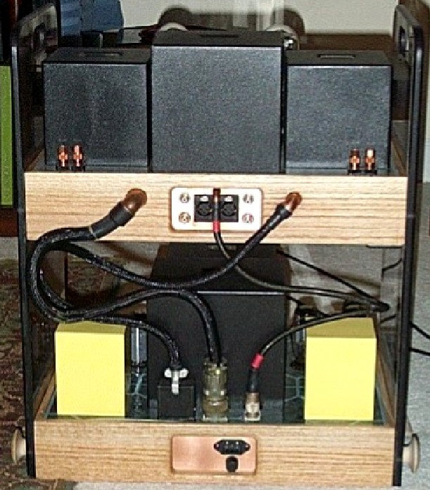
The upper deck is clearly the stereo amplifier while the lower deck is of the companion PSU. The indicator lamp on the amp is connected to the bias supply: if it does not come on immediately when powering up, I will know to abort the power up!!! The toggle switch on the PSU is the standby-operate switch (amber-green). The amp has a wide and very clear response with terrific articulation and resolution, no 'wooliness' or euphony at all. Superb spatial presentation also, the bass is not lacking in punch, extension and control which I am pleased about. SE amps are often regarded as intrinsically weak in this respect. Sounds such as snare brushes and strings complete with fingering noise are crystal clear.
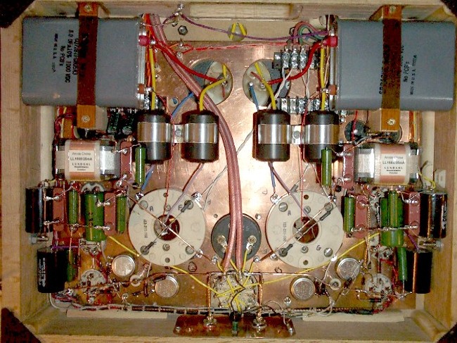
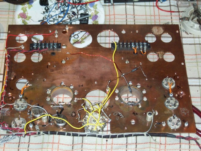
The local B+ bypass film capacitors are clearly visible, also additional paper in oil bypass capacitors for each output stage. In fact, you may be able to see how the 1000V film capacitors in the centre go directly from the B+ terminals on the output transformers to the centre of the resistors which form a centre tap across the each 845 filament.
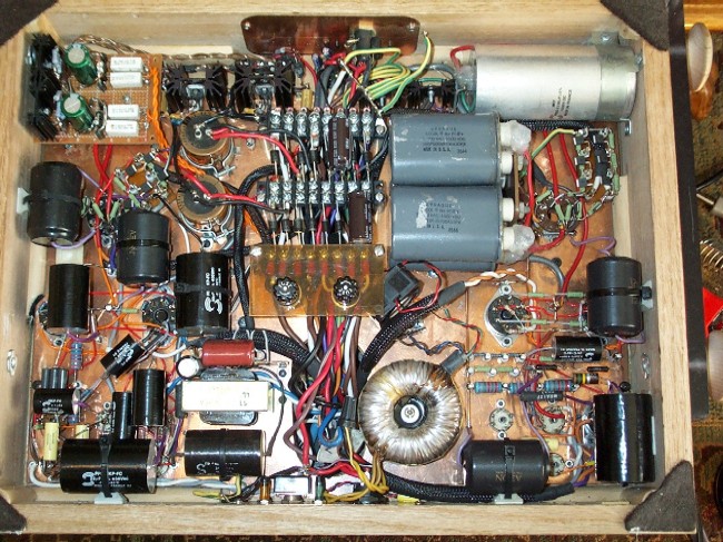
The power supply. Starting from top right going CW we have: The input DC rectifier and filter for the 1000V/150mA supply. The oil caps are a block of four 1µF/1500F caps as the reservoir and the aluminum can is a 51µF/1500V Solen film cap for input smoothing. Below that are the 1000V series pass tubes and the error amplifier with gas reference tubes. Next is the line and standby-operate switches. The small choke is for the bias supply (silicon rectified) which is stabilised at -150V using a gas tube. To the left is the pre-drive regulator (320V/14mA) and the error amp for the drive regulator. Above that are the series pass tubes for the drive stage supply (270V/60mA). Above these are the drive and pre-drive stage input DC rectifier and smoothing components. In the centre is a bank of Schottky diodes serving the DC filament and heater supplies. The heat-sinks for the 45 filament regulators are just visible at the top left while the 845 filament regulators are above the diode bank. Attached to the lower end of the diode bank is a lexan plate holding the B+ fuses which are located electrically ahead of the rectifiers
 .
.
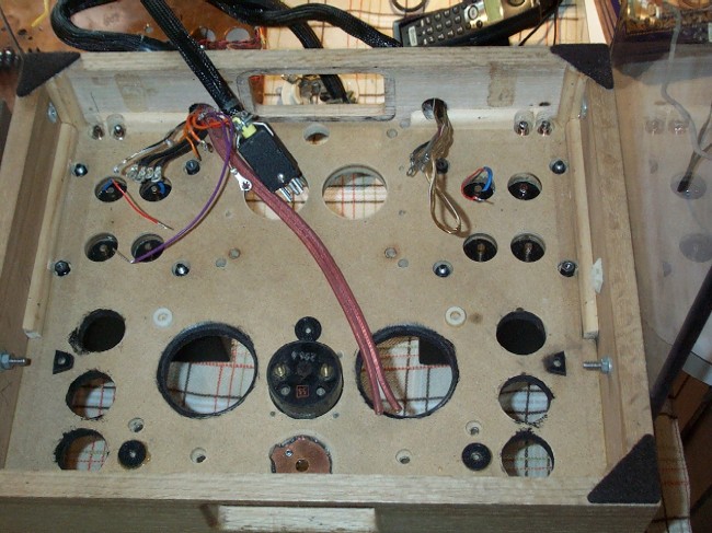
The chassis are constructed using an oak frame and an MDF deck. The top is finished with linoleum. There is plenty of clearance for free convection around the valves. The valve sockets are mounted on a copper sub chassis. I did most of the electronic construction before (finally) mounting the sub chassis. A nice feature of using the copper sub chassis is that it permits a free convection path (between the chassis and the deck) around each valve without leaving any electrical contacts exposed around the tube base. Especially good with the 845 having 1000V on the anode!
The umbilical connectors are located behind the main B+ transformer. Multi pin for low current heaters, bias and lower B+, Jones for the 845 and 45 filaments, also a two pin connector for the 1000V B+. The 1000V wires are run inside a heavy PVC tube for additional insulation and ruggedness. All power supplies are being wired separately to each channel with a local bypass capacitor right at the point of take-off. Further, the ground and bias lines are duplicated to assure reliability.
Performance:
Having iterated the output transformer design twice and built a (messy) test amplifier, I measured the performance: Driven to 25W, the -3dB points are around 30Hz and 95kHz. At less than full power, the LF extends to 0.5dB down at 20Hz. I am getting 28W into 8 Ohms at 3% THD @ 1kHz. The performance is tremendously rewarding after all the hours spent winding.
Development Narrative: (What happened and how, as I went.......)
6/23/2001:) After several months of deliberation I am now really getting to grips with this project. The vacillation has mostly been because I have decided to design and wind my own output transformers. I fairly soon came to the conclusion that I wanted to use double C cores for this job but they are quite hard to find in a suitable size. This stopped me in my tracks for a while. However, a 'phone call to Jenny Booth of Booth transformers, UK put me onto a surplus dealer in London who had just what I was looking for! Size 7024-2 Hipersil C cores.
6/24/2001:) I have built the drive circuit on my breadboard set-up and done some tests. The results are really pleasing, especially since they are achieved without the aid of negative feedback. (OK if you are sharp, you will notice the unbypassed cathode resistors on the pre-drive stage which provide some 0.9dB of degeneration in that stage only.) Most credit really, goes to the performance of the Bartolucci interstage transformer.
THD at 100Vrms / 1kHz 0.08%; -0.5dB: 20Hz to 36kHz; -3dB:<10Hz to 110kHz. The waveform at 10Hz / 100Vrms is good. In addition to this the square waveform at 10kHz is really excellent and with very little rounding and no ringing at-all. These tests were performed into a 50k / 120pF load. The 120pF is a little higher than the total input capacitance of an 845 which they are to drive. The measurements were taken using a HP339a distortion test set which has been calibrated within the last two years.
6/28/2001:) I took at look at the distortion residual from the drive circuit (available as an output from the 339a). Although the THD is extremely small, I was not too happy with the appearance of the residual which, (displayed on a dual channel CRO over the fundamental) indicated strong presence of 3rd harmonic in the spectrum. So I tried reducing the bias current in the EL34 and at 35mA, the residual became a very clean sine wave of twice the fundamental frequency meaning the THD is almost entirely 2nd harmonic. This occurred at 35mA. The lowest THD occurred at 64mA, any further increase in current causing the THD to rise once again. The corresponding SMPTE intermodulation distortion readings were 0.5%, 64mA and 1.1%, 35mA. It will be most interesting to see how varying the drive stage bias current affect the performance of the completed amplifier and more significantly, the sound.
{SMPTE intermodulation distortion test: The amplifier is fed a dual tone signal, 60Hz and 7kHz in a 4:1 ratio. The intermodulation distortion is the percentage of the residual RMS measured at the output (after filtering the test tones out) compared with the total RMS measured at the output.}
7/14/2001:) The 4 sets of C cores have arrived and I have made the bobbin for the first transformer using fish paper. The end cheeks are glued to the former using epoxy. I also have obtained the various gauges of double-enameled wire, a reel of mylar tape and have ordered the teflon film (at hideous expense!). I am now working on a coil winder...
7/23/2001:) I have started winding, go to "Transformer" page for more details.
7/30/2001:) MKI transformer complete, narrative and test results at "Transformer" page.
8/3/2001:) Photographs of OPT with 845 test amp. On the bench I am getting 24.5W into 8 Ohms at 3% THD. This is good for an SE amp and I am very pleased. I may take some IMD measurements later for the sake of interest.
8/16/2001:) MKII transformer details at 'Transformer' page.
9/8/2001:) MKIII transformer performance at 'Transformer' page.
9/21/2001:) Construction started, see photos above.
10/14/2001:) Amp powered up for the first time, stereo SE DH triodes, glorious!
Topology:
I recently re-built this amplifier, replacing the 6SN7 SRPP input stage with a new input topology using 76s and replaced the EL34 driver stage with a 45 DHT. The design of the first stage is worthy of some explanation:
 |
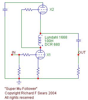 |
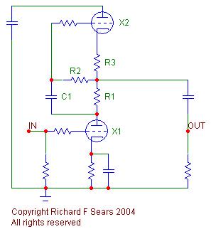
| A conventional mu follower uses a resistor (R1) between the anode of X1 (gain valve) and the cathode of X2 (current source and cathode follower) across which the signal to drive X2 is developed. The drive signal is condenser coupled (C1) to X2, the grid of which is connected via a leak resistor (R2) to the lower end of a bias resistor (R3) placed in the cathode circuit of the X2. There are two limitations to the conventional approach: 1/ the resistor value (R1) and thus the current source drive signal amplitude is limited by practical considerations; 2/ the performance of a triode as a current source is limited, a pentode or fet would be superior. |
What I have done is to place a choke between the anode of the X1 and the cathode of X2, nicely eliminating the need for a coupling condenser. (Note, I 'got lucky' in locating a choke, the dc resistance value of which was 680 ohms, suitable to bias the current source triode.) The near flat slope of the resulting load on the gain valve allows a maximal signal to be applied to the grid of the current source valve. This maximizes the effectiveness of the upper triode as a current source, resulting in not only extremely high sink impedance looking into the cathode but also extremely low source impedance from the cathode of the upper valve.
|
The load 'seen' by the Super mu Follower stage (for example, subsequent stage grid resistor) has a minimal effect on the 'flatness' of the load seen by the gain triode. This has two nice consequences: 1/ the gain approaches the mu of the valve extremely closely and 2/ the linearity of the valve is little affected by the load. There is a third, less obvious benefit: Because the load seen by the gain valve is very close to a true current source (that is the load approaches an infinite ohmic value), the resistance of the cathode resistor as a fraction of the load is trivial, thus the stage does not require a cathode bypass condenser to operate at maximum effectiveness. This renders the use of fixed bias and the consequent complication of dc voltage on the input grid on the Super mu Stage redundant. Consequently this concept is well suited for use as an input stage. Since this idea came out of my head (I did not crib it from the literature), I took the liberty of dubbing it a "Super Mu Follower".
The drive stage uses a transformer loaded fixed bias 45 triode. The input stage is R-C coupled to the grid of the (45). The cathode of the input stage is coupled to the cathode of the 45 via the 680 cathode resistor of the 76, directly to the cathode of the 45. The bias voltage is applied to the 45 via a grid resistor which is terminated at the wiper of the bias voltage control potentiometer. The wiper is decoupled such that the LF corner of the decoupling capacitor 'looking into' the thevenin resistance of the bias supply is less than 5Hz. (The thevenin resistance is due to the resistance from the bias potentiometer wiper directly to ground taken in parallel with the resistance from the bias potentiometer to ground looking back through the bias voltage supply).
The in-phase end of the drive transformer secondary is connected directly to the grid of the 845 which in configured as a fixed bias output stage. The other end of the drive secondary is terminated at the wiper of the bias voltage control potentiometer. Since this node is the out-of-phase side of the drive signal, it is necessary to ensure that it is tightly ac coupled to the cathode of the 845 output valve. I accomplished this using a 120µF photoflash cap, salvaged from a disposable camera. This capacitor is bypassed using 4µF and 0.1µF paper-in-oil condensers.
Each stage B+ supply is individually bypassed using a combination of polypropylene film capacitors to get the intended capacity and paper-in-oil condensers to improve the voice. Each bypass combination is connected directly to not just the point of B+ feed to the circuit but in the case of the fixed bias stages, directly to the cathode of the associated valve. In the case of the cathode bias input stage, the bypass return in connected directly to the ground end of the cathode resistor.
The power supply is a monster! I had the primary power transformer supplied as a custom unit by Bartolucci and weighs 40lb It has just the high-tension and rectifier windings. The heater / filament transformer (also by Bartolucci) weighs a further 30lb. These two transformers together with the two chokes result in a total "iron" weight for the power supply alone of 80lb!!!! The high-tension transformer will be turned on after the heater transformer using a delay relay. A separate tube voltage regulator is used to supply each stage. A 0A2 gas tube is used to stabilize the bias voltage however, silicon rectifiers are used for this critical supply rail. The B+ rails both have C-L-C input filters. The rectification for each B+ rail is accomplished using a hybrid bridge. Fast silicon diodes form the negative arms while GZ37s form the positive arms. This arrangement confers the slow warm-up of the GZ37 yet remains within the peak inverse voltage rating. To further protect the GZ37s, I am including fast silicon diodes in each plate circuit of the rectifiers, also. In this way, the GZ37s never "see" the inverse voltage. The reservoir capacitors are 4µF and the smoothing capacitors are 51µF. The output stage supply uses a pair of 6AS7s in parallel as series pass elements. The reference voltage is developed across a string of three 0A2s which form the cathode circuit for an EL34. The error voltage is applied to the EL34 grid. The amplified error signal at the plate of the EL34 is applied to the grid of the first section of a 12AT7 which in turn drives the second section the cathode to preserve the inverse phase. The further amplified error signal at the plate of the second section of the 12AT7 is applied to the grids of the 6AS7s. Again, I have done a great deal of modeling of this design mostly to ensure that it can handle the very large input voltage swings which result from line variations multiplied by the power transformer ratio and capacitor input raw DC supply. The drive stage regulators both use cascode error amplifiers with 85A2s (0G3) to develop the reference voltage. The drive stage regulator uses two parallel E34Ls while the pre-drive stage uses a 6H30.
The filament supplies for the 45s and the 845s use Linear Technology 3 pin voltage regulators, configured as current regulators. The advantages are:
1/ There is no switch on current surge to challenge the fragile (and expensive) filaments
2/ The resistance 'looking back into' a current regulator is much higher than that of a voltage regulator. This overcomes the ac short circuit that a voltage regulator presents to the end-to-end signal which develops along the filament as a consequence of the bias gradient* which, I suspect may be one reason why direct heated triodes energised using current regulation are considered to sound better.
* The bias gradient results from the DC voltage applied to the filament. For example, if we use a pair of equal resistors to create a cathode centre tap then in the case of the 845, the negative end of the filament will be biased at 5 volts less than nominal while the positive end will be biased at 5 volts more than nominal.
You can see the schematics by clicking on the hyperlinks below but since I will want to publish the project in VTV at some point, I have hidden the component values. I hope however, you might find the topology details interesting.
Click here to see the audio circuit:
Click here to see the power supply regulation circuit: