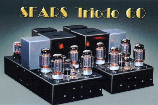
This was the first incarnation of my KT88 mono-blocks. The artistic rendition arrived in my email as a complete surprise from Steven Spicer (see links page, Kiewa Valley Stereo). I had sent him the photograph and he was moved to do this! Steven is the author of the excellent "Firsts in High Fidelity", the products & history of H.J. Leak & Co. Ltd. Published by Audio Amateur Press, ISBN 1-882580-31-1
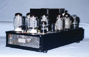
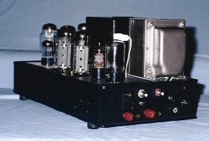
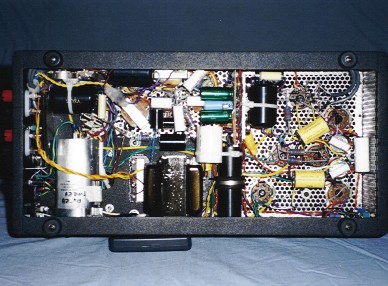
60 Watt triode connected KT88 mono-block. The power bandwidth is 10Hz to 50kHz. The drive topology is two DC coupled long-tailed-pairs, 6SL7 and 6SN7. The second pair features Shunt Regulated Push Pull active loads. I have dubbed this topology Differential SRPP Pair (DSRPPP). I have not seen it published before. Separate vacuum tube regulation is provided each for the drive stage, output stage and negative rails. It accepts both balanced and unbalanced inputs. The output transformer is a Bartolucci Model 106 (now Model 555). Am I permitted to say that these are the best sounding amps I had heard until I started listening to my 845 test amp?
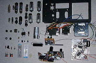
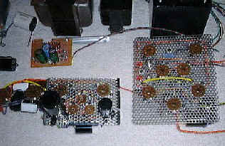
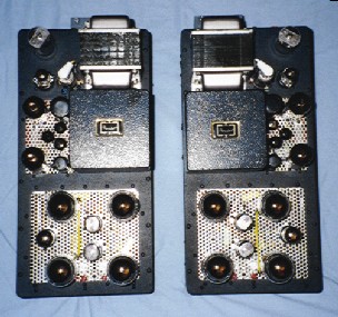
Pictures show the "parts kit" ready for assembly to the chassis. All circuitry was pre-build as sub-assemblies. The right hand picture shows: Top left, DC heater regulators; lower left, high tension regulators; right, amplifier.
Click here to see Amplifier topology:
Click here to see Regulator topology:
Click here to see PSU topology:
Design Approach.
It is well known that odd order harmonics are more readily detected by the human ear than even order harmonics. To gain an appreciation of this, try the following experiment:
Sit at a piano (preferably in good tune and without false
beats and other defects) and play A below middle C (220Hz) and then play both
A220 and A440 simultaneously (one octave thus the fundamental and 2nd
harmonic) a richening of the tone will be apparent. It is possible to envisage that if you were seated out of
sight of the keyboard while another strikes the octave, it would not be obvious
whether a single note or an octave has been struck. However, if we were now to repeat the exercise using A220 and
E above A440 (660Hz thus the third harmonic on A220) there would be no doubt
at-all as to whether a single tone has been struck or the fundamental and 3rd
harmonic struck simultaneously.1 Further, Hamm observed
that odd order harmonics cause the sound to be perceived as “stopped” or
“covered” whereas even order harmonics are experienced as lending
body to the sound making it “fuller” or more “choral” in aspect.2
Initially, the intention was to design an ultra-linear (also known as partial triode) amplifier but I soon came to correlate the behavior of triodes with what I had read and experienced regarding relative the sensitivity of human hearing to odd and even order harmonics. When viewed in the light of this information, the predisposition of triodes to produce predominantly second order harmonic distortion may partly explain why the sound of triodes is preferable to that of most, if not all, other amplification devices.
A further important consideration is that the natural harmonics of musical instruments tend to mask harmonic distortion whereas intermodulation distortion is clearly audible and disturbing. Being less concerned about total harmonic distortion (THD) combined with other considerations (discussed below) allowed me to dispense with global negative feedback. However, I did concern myself with intermodulation distortion (IMD).
The predisposition of a triode to produce predominantly second harmonic distortion is due to the power law characteristic of the plate voltage-current relationship exhibited by triode devices as elucidated by Child’s law viz; IµV3/2
This gives rise to the characteristic “to the right and up” plate bend of the grid lines on the plate curves. If we plot a realistic load line on a set of typical triode plate curves, the right hand end will be in a region of asymmetrical compression of the grid lines caused by the plate curvature. This non-linear transfer characteristic will result in a waveform that is asymmetrically distorted about the x-axis, having higher negative going peaks than positive going. If we imagine now that the transfer characteristic is linear (uncompressed toward cut-off) we will obtain an undistorted sinewave of the same frequency. Algebraic subtraction of the distorted resultant from the undistorted waveform results in a new frequency double that of the fundamental and of lesser amplitude, a second harmonic.
Pentodes behave exponentially, giving rise to odd order harmonics. (A succession of exponential curves is a square wave with the higher order harmonics absent3 and a square wave expands as a Fourier series of odd order harmonics.)
It follows then, that the use of triodes in a push-pull circuit so as to minimize the residual characteristic triode coloration of the sound through cancellation of even order harmonics in the output stage is one approach to hi-fi reproduction.
I embarked upon the development of a drive circuit having wide bandwidth, low output impedance, low distortion - preferably predominantly even order - and near perfect balance.
I was determined to develop a fully balanced design, that is a topology which will produce balanced phase and inverse-phase signals from an unbalanced source at the first stage and from there to summation in the output transformer. Many permutations of Long-Tailed Pair4 (hereafter referred to as LTP) were analyzed, built and tested. It was not difficult to achieve near perfect balance, excellent bandwidth, low distortion and adequate gain in one stage. However, the distortion residual (isolated from the fundamental using a HP339a distortion analyzer) always showed evidence of both odd and even order harmonics. Further work revealed that suitably designed Shunt Regulated Push-Pull (hereafter referred to as SRPP) active loads for the 6SN7 LTP can provide sufficiently low output impedance to drive parallel pairs of triode connected KT88s with more than adequate swing at very low level of total harmonic distortion. Further, to the best that I could observe when viewing the THD residual against the fundamental on a dual trace oscilloscope, the THD residual from this topology appeared to be primarily second harmonic. Since a spectrum analyzer was not available, this assertion has not been confirmed. However, one might reasonable expect that a very sparse spectrum of distortion components from the drive stage might reduce intermodulation components. This is borne out somewhat by the measurements; THD,1.7% : IMD,2.5% at 60W. Audio Cyclopedia5 suggests that the ratio of IMD to THD in a triode PP amplifier tends to be in the range of 3.2 to 3.8. The ratio for my design is 2.5/1.7 =1.47:1 which I think, tends to support my assertion.
The balance of the 6SN7 SRPP LTP was not commensurate with the intention of maximizing even order harmonic cancellation in the output stage, also a further 10dB or so of gain was required. The obvious solution was to add a LTP input stage in front of the drive stage, both to increase the gain and to improve the balance. After some iterative fumbling around with curves, I established that a 6SL7 would mesh very nicely with an operating point as a function of the 6SN7 grid voltage, thereby permitting DC coupling. However, the gain would be too high. In addition, the HT voltage needed to be reduced to a more suitable level for this first stage. At this point, I hit upon the concept of connecting the 6SL7 plate loads to their respective SRPP cathodes. This circuit node is at an appropriate DC potential and permits reduction of the gain to more-or-less exactly what the required level by degeneration of the swing in the first stage plate loads. This of course, is negative feedback. I felt able to live with this approach since the feedback is applied around a simple DC coupled loop for which at audio frequencies, phase shift would not be problematic. Also, unlike applying global feedback from the output transformer secondary the fed-back signal would be entirely due to the internal voltage gain process and not influenced by the back e.m.f. from the loudspeakers(s). It has been be argued that in the back e.m.f. entering the amplifier’s feedback loop via the output terminals, the amplifier is attempting to correct not only for internal non-linearity, but also for an erroneous back e.m.f. signal which will have phase anomalies due to the inductance of the voice coil, and the reactance of the crossover network(s) the loudspeaker cable.6 This argument rings true for me and bolstered my determination not to employ global negative feedback.
So, the drive stage had matured; fully balanced with a swing capability exceeding 160% of that required to fully drive the KT88s, low output impedance, excellent bandwidth, the correct amount of gain which generates substantively 2nd harmonic distortion. An additional benefit of this drive topology is that not only is the balance “perfect” (i.e. better than 0.1dB) but also the THD residual measures and looks the same at both output terminals. I have not observed these three properties coalesce with any of the alternate topologies and permutations thereof that were investigated as a part of the design process. (Note, at this juncture I had not evaluated a transformer topology.) Thus arose the hope of developing a push-pull amplifier with zero global negative feedback that would have low distortion, lots of power and good bandwidth. It also became very clear to me that the design of the power supply is at least as important as that of the audio circuit. An amplifier is “merely” a device which increases the energy of a signal to a level at which it may be re-transduced into sound. The amplifier does this by modulating current from a voltage source with the musical signal. It thus follows that the voltage source must be as constant and clean as possible. A well-designed (tube) voltage regulator can provide a source impedance of less than 1ohm from below 10Hz to frequencies beyond the audible range together with extremely high levels of ripple and noise rejection.1 Author. Personal Email communication to Steven Spicer, November 2000
2 Hamm, Russell O. "Tubes Versus Transistors - Is There An Audible Difference?," Audio Engineering Society Journal, may1973, Volume 21, Number4
3 Jones, Morgan. Valve Amplifiers Ch2, "Basic Building Blocks," Oxford: Newnes, 1995
4 Blumlein, Alan D. "Improvements in or relating to Thermionic Valve Amplifying Circuit Arrangements," UK Patent Specification Number 482740.
5 Tremaine, Howard M. Audio Cyclopedia, Howard W. Sams, 1978
6 Hayes, Kevin. "Some Thoughts on Amplifier Design," Durham: Valve Amplification Company.