To the casual browser, my designs may appear very complex. This is because I am a firm believer in the sonic merits of well-designed regulated power supplies. This belief has its' roots in a test-bench experience. I was working on a differential cascode circuit operating from 650V. During the course of a day, I saw the 650V vary from something like 580V to 680V. Apart from the traces swinging all over the 'scope screen while I was trying to make measurements, the consequent variation in operating point was not acceptable to me. What is the point in carefully setting the operating conditions of a circuit, only to have the antics of the utility company render the effort wasted? With lower voltage circuits of course, the issue is less critical but many of my circuits do require high B+ levels. Most of all though, the source impedance characteristics of a regulated supply are both much lower than and much "flatter" than those of a passive supply. In fact, the power supplies have a fairly simple topology, simply replicated for each supply voltage level. I feel that my audio circuits are "properly" clean.
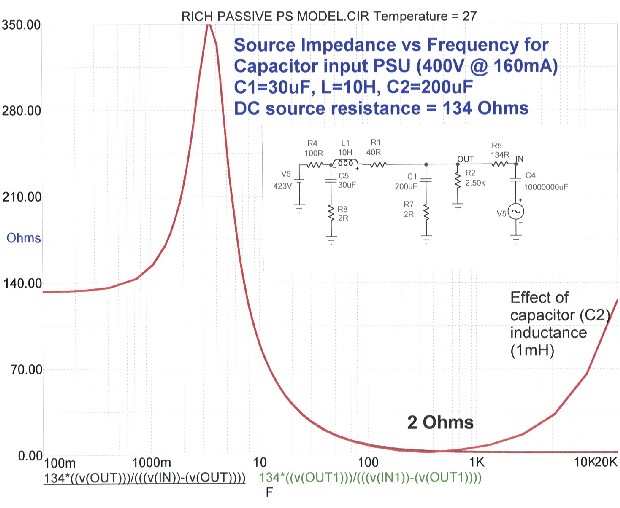
The first curve shows the Z vs F performance of a typical capacitor input PSU. The rectifier and transformer DC resistances are lumped as 100 Ohms (which is on the low side if using a tube rectifier). R1 (40 Ohms) is the choke DCR. The LF impedance spike is typical of such a supply. Furthermore, the supply impedance does not fall even to the DC value for the regulated PSU until 100Hz. IF the smoothing capacitor is truly non-inductive then the impedance over the flat portion of the curve is governed by the equivalent series resistance which I have included in the model as 2 Ohms. BUT 1mH of inductance is sufficient to cause the impedance to curve back up to 130-140 Ohms at 20kHz. The LF corner frequency can be reduced by increasing the capacitance however, LF resonance will remain. This may explain why some people think that tube amps have soft or "flabby" bass when compared with solid state. It does not have to be so. While passive supplies may appear simple, the operation and performance is actually very tricky and totally dependent on component quality.
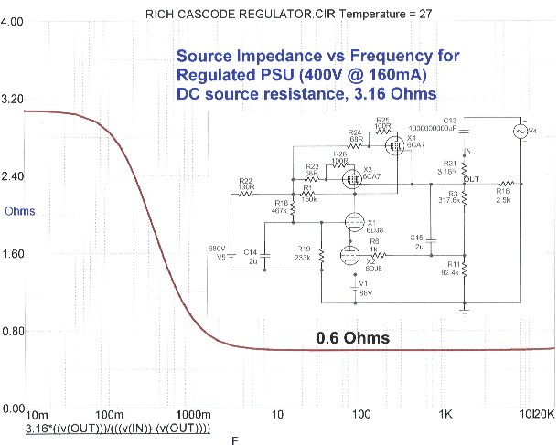
By contrast, the regulated PSU has a uniform source impedance of 0.6 Ohms from 10Hz to 20kHz. It rises towards DC due to the LF corner of the error feedback capacitor, C15. I find that my amps perform FAR better in the bass region than any solid state amps I have heard, and of course, far better than solid state in all other respects except one: HEAT. The series pass tubes (apart from the additional heater dissipation) dissipate much heat. That is why my integrated amp features a Hexfet pass element. It can operate at a much lower voltage differential and thus dissipates much less heat. I refer to this amp as my "summer amp"! Another point in favour of regulation is that the ripple rejection can be designed to be high enough to eliminate a choke in the input DC supply. Using a single stage cascode error amp (per Kevin Kennedy) and a pentode series pass element with a filtered screen grid supply, 60dB of ripple rejection is easily attained. I recently designed a PSU for a friend which uses triode pass elements with the cascode error amp. I achieved 60dB ripple rejection by including a negative ripple feed-forward path to the upper grid of the cascode thereby enabling him to omit the choke. By the way, if I design a circuit for somebody, I also prove it out on the bench.
Please note that you can download free Duncan Monroe's very useful passive PSU designer. Look for Duncan's link on my tube links page.